
Trail Counter Installation and Deployment Guide
This guide covers the recommended installation practices for Waypoint's solar-powered, vision-based trail counters: where to place the camera, how high to mount it, how to aim it, and how to orient the solar panel for reliable year-round operation.
Every recommendation here comes from our first 10 field deployments across multi-use trails, mountain bike parks, pedestrian bridges, and street corridors. We include examples of installations that worked well — and a few that didn't — so partners performing their own installations can avoid the problems we've already encountered.
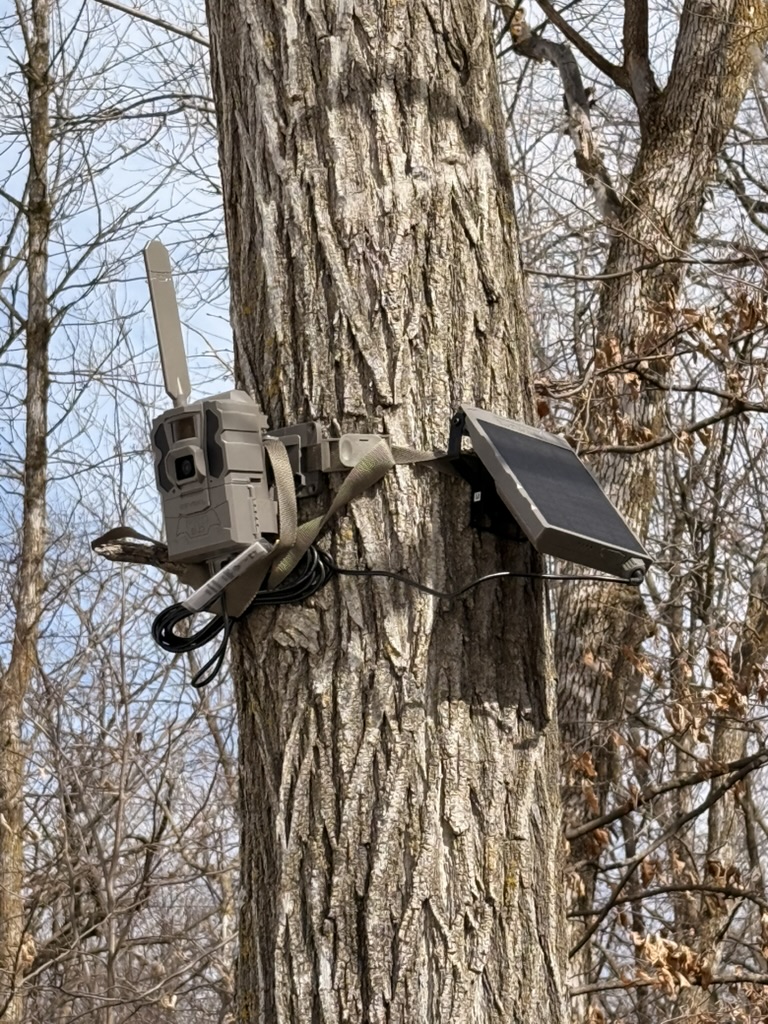
A typical completed installation: camera and solar panel on a single mounting strap, connected by a charging cable.
What's in a Deployment Kit
Each Waypoint deployment kit ships preconfigured — the camera is registered to our cloud platform and its detection software is set up before it reaches you. A typical kit contains:
- •Solar cellular trail camera — preconfigured with custom registration and monitoring software
- •Lithium battery cartridge — usually shipped installed in the camera
- •Tree/pole mounting bracket — allows fine aim adjustment after strapping
- •Solar panel (standard or extended) — recharges the battery for indefinite operation; sized to the expected activity volume at the site (see Choosing a Solar Panel)
- •Charging cable — connects the solar panel to the camera
- •Mounting strap — secures both the camera bracket and solar panel to a tree or pole
Choosing a Camera Location
Waypoint cameras sense motion, capture images, and send them to cloud-based computer vision models that count and classify activity. Because the system observes a scene rather than a single beam-break point, it can monitor more than just narrow trail segments. Location selection starts with one question: are you monitoring a path or a space?
Paths
Trails, sidewalks, and pedestrian corridors where subjects move along a defined line of travel. Most of this guide addresses path installations, where camera distance and aiming angle determine count reliability.
Spaces
Trail convergences, trailheads, picnic areas, and parking lots where activity occurs across an open area. For spaces, simply frame the full area of study — as long as the field of view captures the target subjects, our models can run analytics on it.
This flexibility is a core advantage of vision-based counting over infrared sensors, which only register beam-break events at a single point. See our comparison of vision-based vs infrared counters for more detail.
Distance to Subjects: 15–70 Feet
Install the camera no closer than 15 feet from the trail. Subjects passing closer than 15 feet cross the frame too quickly and fill too much of it, which reduces capture reliability and can lead to missed counts.
Install the camera no farther than 70 feet from the target path. Beyond that range, subjects appear too small in the frame to be reliably detected and classified.
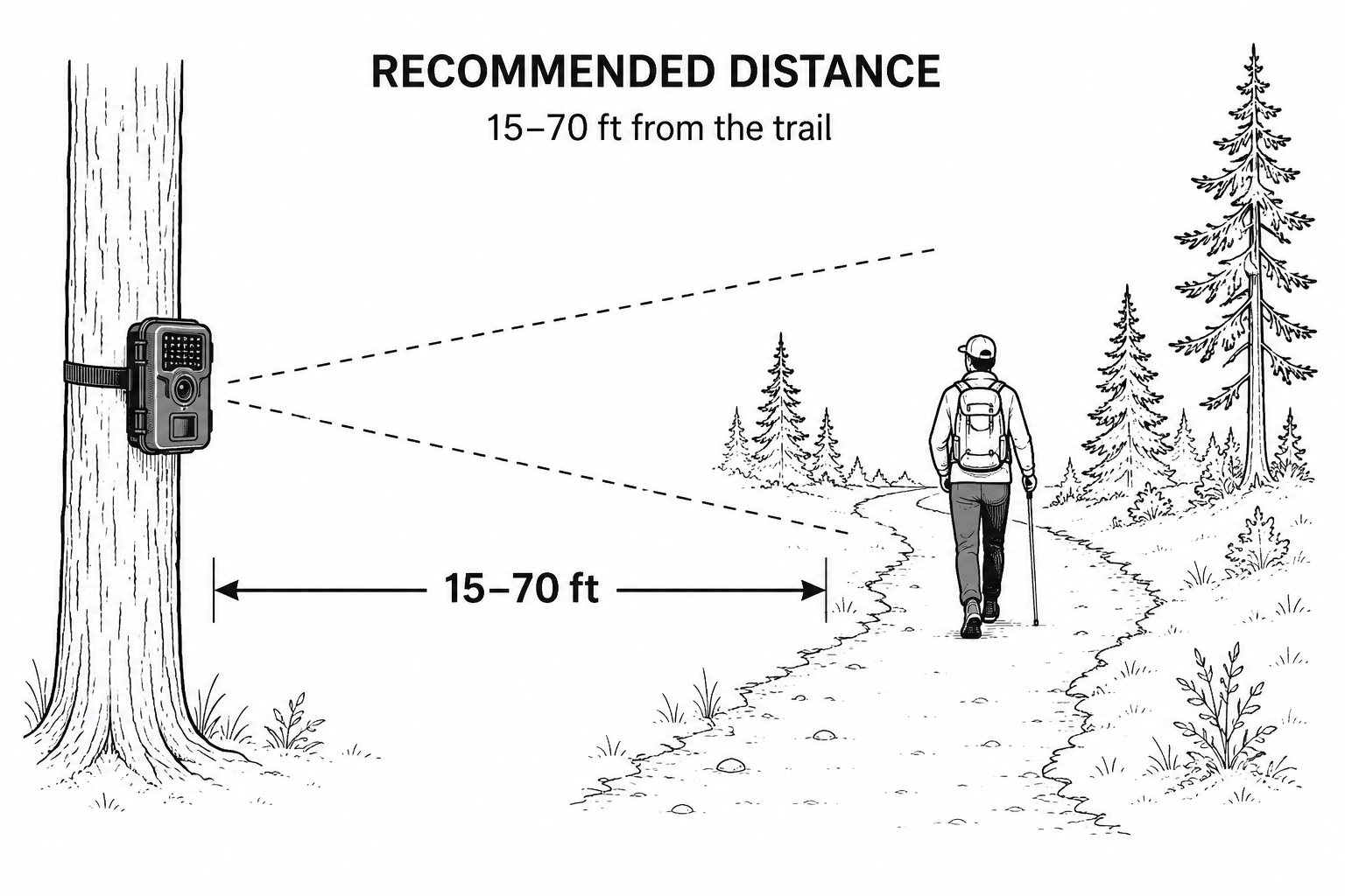
The reliable detection envelope: mount the camera 15–70 ft from the line of travel.
Aiming Angle: Maximize Time in Frame
The goal of camera aim is to maximize the time each subject spends inside the frame. More time in frame means more capture opportunities, which improves both count accuracy and directionality analysis.
The camera's field of view is 60 degrees. That geometry means the closer the camera is to the trail, the more it must be angled up-trail or down-trail to keep subjects in view long enough:
Close to the trail (~15 ft)
Aim the camera 30–60 degrees up-trail or down-trail so a long stretch of the path falls within the frame. A perpendicular aim at this distance gives subjects only a fraction of a second in view.
Far from the trail (~70 ft)
The camera can — and should — be aimed perpendicular (90 degrees) to the trail. At this distance the 60-degree field of view already covers a long section of path.
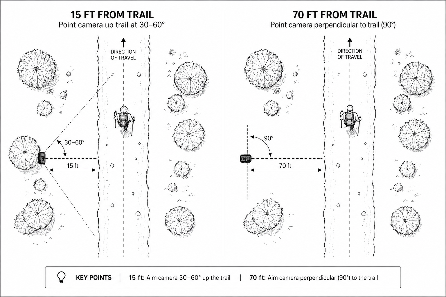
Overhead view: close installations angle along the trail; distant installations aim perpendicular.
Mounting Height: 7–15 Feet
The primary purpose of mounting height is to deter casual theft and tampering. We recommend using a ladder to install cameras above 7 feet — high enough that the camera is out of reach and largely out of notice.
We also recommend not exceeding 15 feet. Beyond that, installation becomes a safety hazard and the steep downward angle starts to work against the camera's detection geometry. Within the 7–15 ft band, angle the camera slightly downward toward the trail.
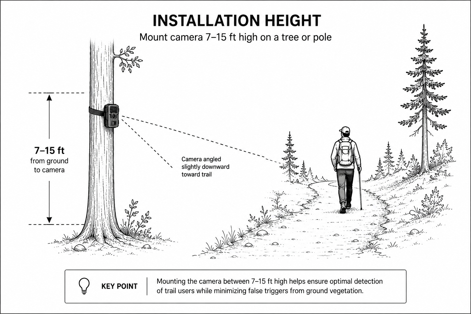
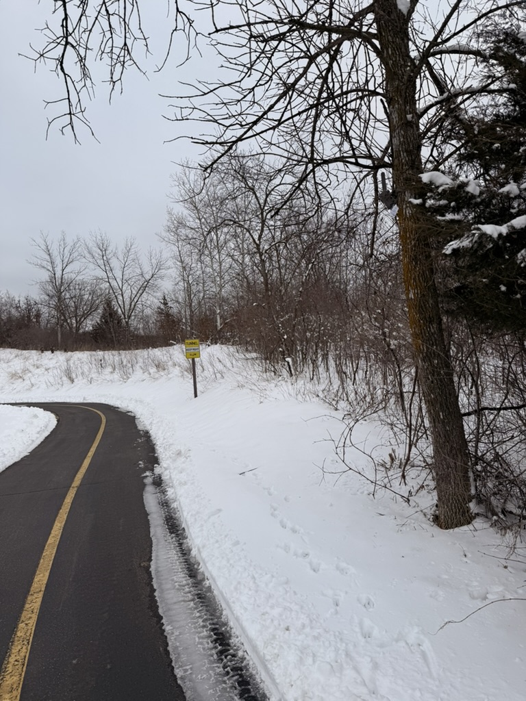
Height doubles as concealment
A camera mounted above 7 feet sits outside the natural sight line of passing trail users. In this installation, the camera is mounted in the tree on the right side of the frame — most visitors never notice it. Less attention means less tampering risk and less behavioral influence on the activity being measured.
Choosing a Solar Panel: Standard vs. Extended
Power consumption scales with activity. Every passage triggers an image capture and a cellular upload, so a camera on a busy corridor draws far more energy per day than one on a quiet natural-area trail. Waypoint deployment kits ship with one of two solar panel options, selected to match the expected daily volume at the site:
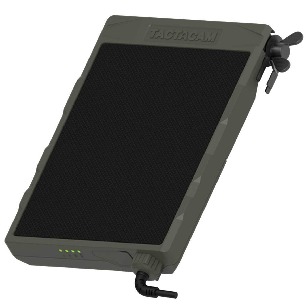
Standard Solar Panel
~5W panel · one integrated 4Ah battery
The default for most trail, park, and natural-area deployments. Compact, strap-mounts alongside the camera, and keeps the camera charged at low-to-moderate activity levels.
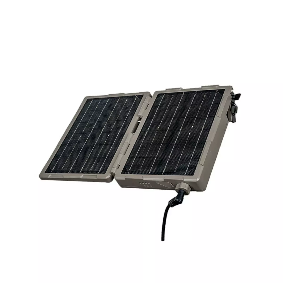
Extended Solar Panel
~10W hinged dual panel · two integrated 4Ah batteries
Roughly double the charging capacity and battery reserve of the standard panel — for high-volume sites where frequent captures and uploads would otherwise outpace charging, and for sites with limited winter sun.
| Average Daily Passages | Typical Application | Solar Recommendation |
|---|---|---|
| < 100/day | Remote trails, natural areas, low-use recreation | Standard Solar Panel |
| 100–500/day | Popular trails, bike parks, neighborhood paths | Standard Solar Panel |
| 500–1,000/day | Busy trails, pedestrian paths, trailheads | Extended Solar Panel Recommended |
| 1,000+/day | High-use pedestrian areas, roads & vehicle monitoring | Extended Solar Panel Strongly Recommended |
When in doubt, size up. If you are unsure of a site's volume, if the panel location will see partial shade, or if the deployment runs through winter, choose the extended panel. Regardless of panel size, orientation and an unobstructed view of the sun (below) matter more than anything else.
Solar Panel Orientation
The solar panel recharges the camera whenever sun is available, allowing the system to operate indefinitely under good conditions. In the continental United States the sun tracks across the southern sky, so:
- •Face the panel south, and
- •Tilt it 30–45 degrees from flat for good year-round performance. If you can adjust seasonally, increase tilt in winter and decrease it in summer.
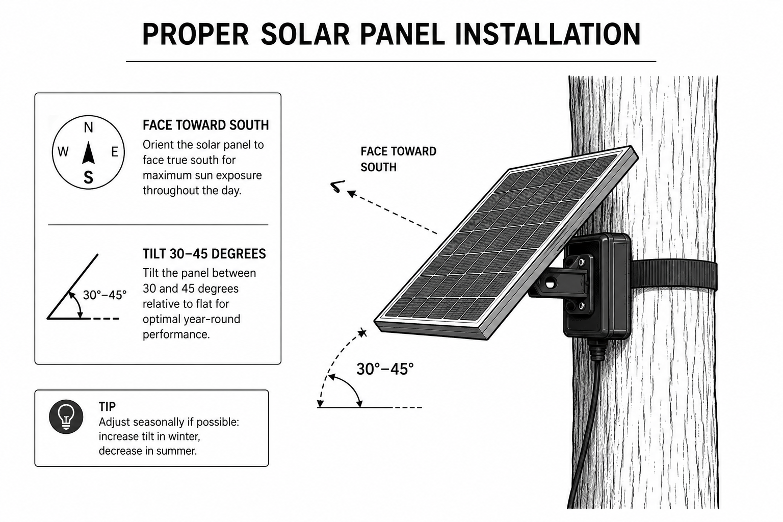
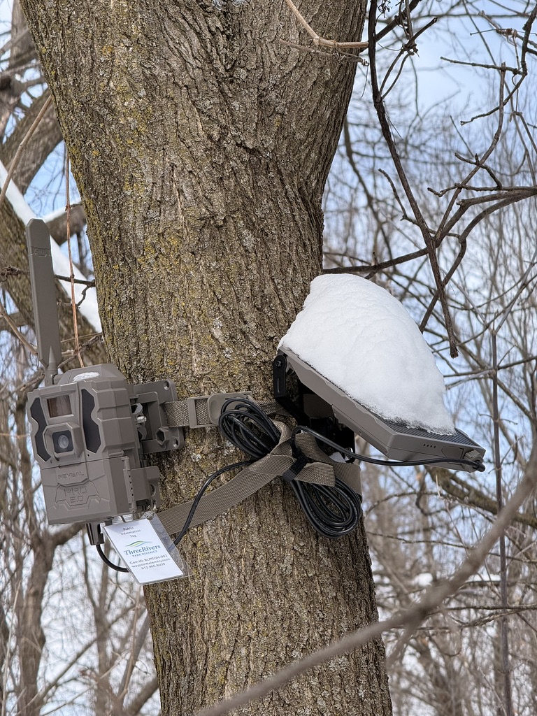
Obstruction is the #1 solar failure mode. The panel needs an unobstructed view of the sun. Even light shadowing from branches and leaves can drastically reduce charging — and on high-volume sites, that leads to camera outages. Snow accumulation, like this winter deployment, has the same effect until it sheds or is cleared. Steeper panel tilt helps snow slide off.
Installation Steps
- 1.Pick your location and mounting structure (tree, pole, or post) using the distance, angle, and height guidance above.
- 2.Thread the solar panel and camera bracket onto the strap before climbing. Doing this on the ground makes the on-ladder work much easier.
- 3.Set the ladder against the mounting structure and wrap the strap — panel and bracket attached — around the tree or pole. Tighten as you finalize the solar panel's direction and tilt and the bracket position.
- 4.Mount the camera onto the bracket. The bracket allows fine aim adjustment after it's strapped in place.
- 5.Connect the solar panel to the camera with the provided charging cable.
- 6.Verify the frame using the camera's live view (press power to see the integrated screen), then finalize and lock the aim.
- 7.Switch the camera into monitoring mode using the onboard menu, following the quick-reference card included with your kit.
- 8.Walk in front of the camera a few times, then confirm with your Waypoint administrator that images are populating in the cloud before leaving the site.
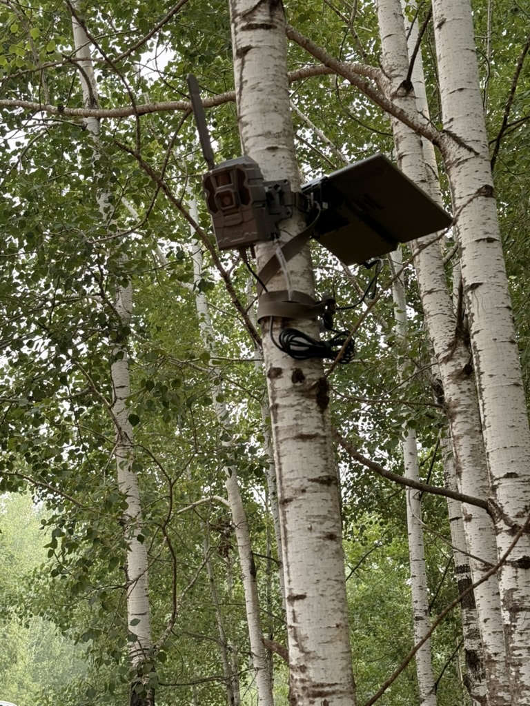
A clean finished mount
Camera and panel share one strap, the bracket provides the final aim, and excess cable is coiled and secured. Tidy cable management matters — dangling cable invites tampering and can swing into frame on windy days, triggering false motion events that our noise filtering then has to discard.
Field Examples: Installations That Worked
These examples come from our field deployments and show the guidance above applied to real sites — including the compromises real sites force.
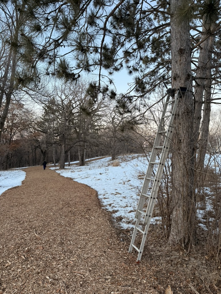
Wood-chip trail, tree mount
The distance to trail is slightly short here, so we aimed the camera down-trail to extend subject dwell time in frame — exactly the close-distance compensation described above. Winter canopy gave the south-facing solar panel direct, unobstructed sun.
Lake Girard deployment →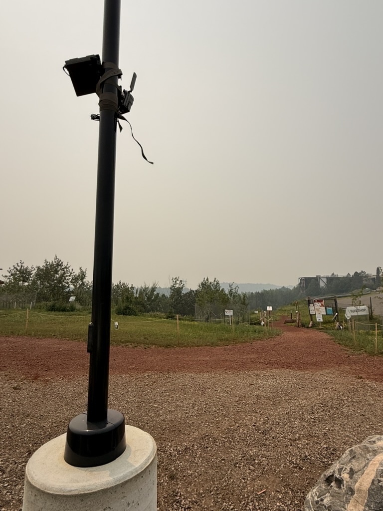
Bike park entrance, pole mount
This light post overlooks the main entrance to a complex bike trail system 50–80 ft away — far enough for a perpendicular aim. One lesson: poles are harder to install against than trees. The strap slips on smooth metal and ladder stability is worse, so budget extra time.
Pedestrian bridge, sign-post mount
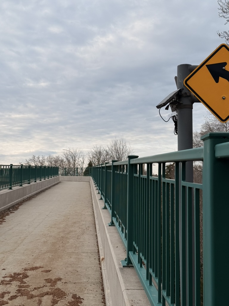
On this freeway-crossing bridge, no placement 15+ ft off the path existed. We adapted by mounting on a sign post aimed almost entirely down-trail. The install captured all traffic successfully, with one tradeoff: left-vs-right directionality was slightly impaired by the head-on aim.
Nine Mile Creek bridge deployment →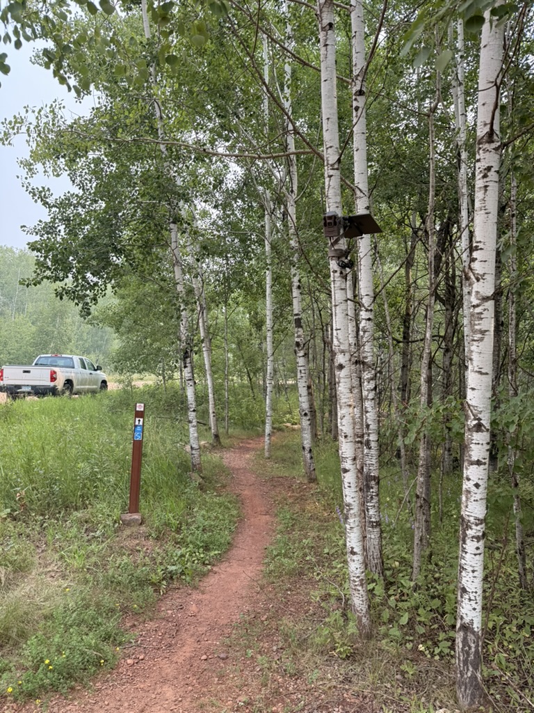
Singletrack in dense vegetation
In heavy summer growth, mounting height does double duty: the camera clears the understory and sees down the trail corridor over vegetation that would block a lower mount. Aim was set along the trail line to maximize time in frame on a fast-moving bike segment.
Field Examples: What to Avoid
Not every early installation went smoothly. These are the mistakes we made so you don't have to.
Too close to the corridor
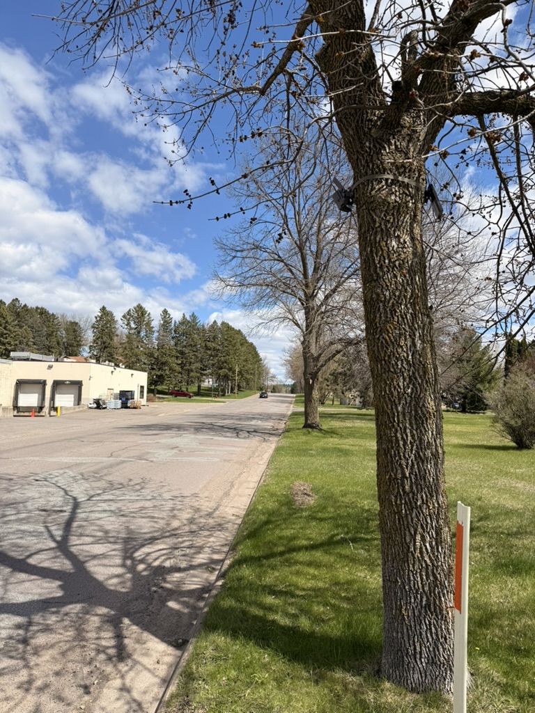
This camera was meant to capture pedestrians along the full length of a street while filtering out vehicles. Mounted nearly on top of the corridor, the 60-degree field of view couldn't hold both near and far subjects. Distance would have solved it.
Obstructed sight lines
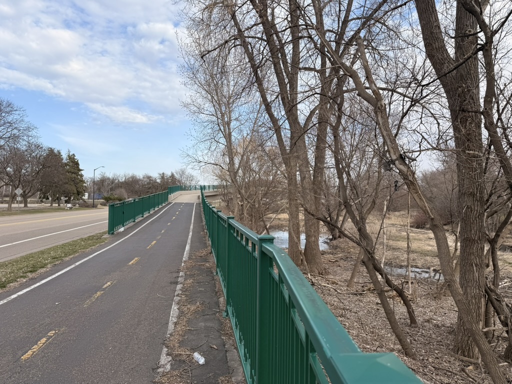
Branches, fences, and bushes between the camera and the path block detections — and vegetation grows over a season. Check the sight line from the camera's actual mounting height, not from the ground, and prefer locations that stay clear year-round.
Close and perpendicular
The worst combination: a camera close to the trail and aimed perpendicular to it. Fast-moving subjects — especially bikes — cross the narrow frame in a fraction of a second and are frequently missed. If you must mount close, angle along the trail.
Deployment Checklist
Run through this list before leaving the site. A two-minute final verification catches almost every common installation problem — and saves a return trip.
- ✓Camera is 15–70 ft from the target path, with the aim angled along the trail if close
- ✓Camera frame verified using the integrated live-view screen
- ✓Camera and solar panel mounted above 7 ft
- ✓Solar panel connected to the camera via the charging cable
- ✓Solar panel facing south, tilted 30–45°, with an unobstructed view of the sun
- ✓Camera switched into monitoring mode via the onboard menu
- ✓Test walks performed and image delivery confirmed in the cloud with your Waypoint administrator
- ✓Laminated public-awareness info cards posted (optional)
Verification Support
Every self-installed camera should be verified before the crew leaves the site. Waypoint provides live verification support during installation — we confirm images are arriving in the cloud, check frame composition, and flag placement issues while you still have the ladder out.
Contact Us for Installation Support →Related Resources
Field Deployments
Detailed reports from the deployments referenced in this guide, including detection results and validation data.
View deployments →Directionality Detection
How camera placement and aim affect the system's ability to measure left-vs-right direction of travel.
Read more →Trail Counter Accuracy
Why installation quality is one of the largest factors in count accuracy, across every counting technology.
Read the guide →Noise Filtering Validation
How the system filters false motion triggers from vegetation, weather, and wildlife — and how good placement reduces them.
See the validation →